The review loop

Import, inspect, verify, compare, report.

  1. 01

    Import and interpret

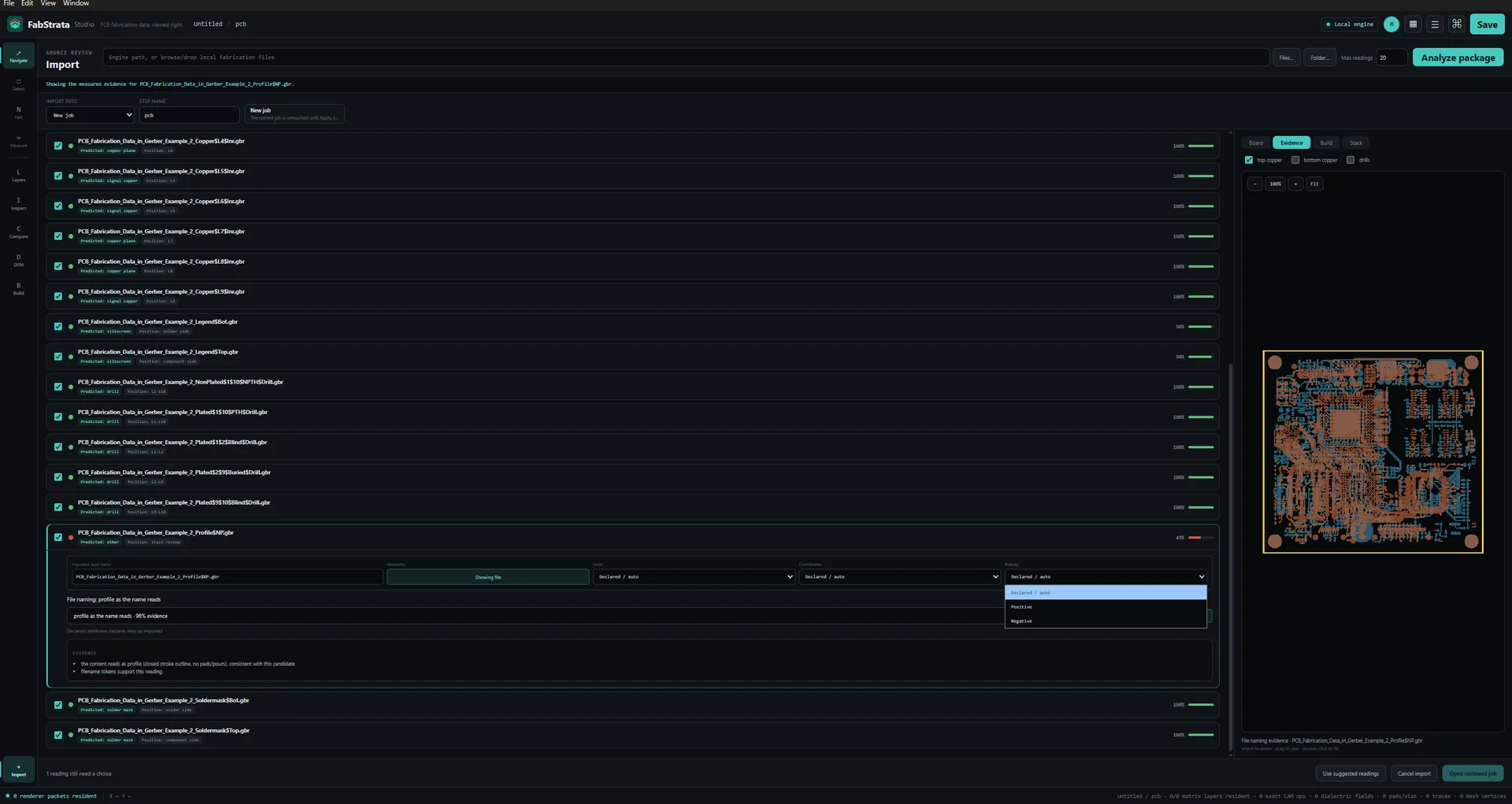
    Every predicted role, position, and parser reading is shown before Apply, with the measured evidence behind it. Ambiguity stays visible and operator-controlled.

  2. 02

    Inspect

    Exact 2D and physical-stackup 3D from the same geometry and the same physical layer order.

  3. 03

    Verify connectivity

    Nets extracted from physical copper and plating, highlighted or isolated across every layer involved, and compared against an IPC-D-356 reference.

  4. 04

    Compare

    Pair the canonical layer matrices of two revision steps and step through added and removed regions with both source layers visible.

  5. 05

    Report

    Save the project, then export an HTML report, a composite PNG, per-layer check films, or a GLB of the physical stack.

01

Input and interpretation

Read the deliverable package the way it was actually written, and see the reasoning before anything is committed to the project.

Current limitsODB++ broader-producer validation and PDF raster/reference fidelity remain open. Any format table must show the limits adjacent to the format, not only on another page.

Show the actual reviewed import UI, its prediction summary, preview, target step, and stack placement.
Reviewed import: predicted role, stack position, and confidence for every file, with the evidence-aligned package preview and the target step beside them.
Gerber X1/X2 and Excellon/XNC
Loose files, folders, and ZIP packages, including drill and route data and Gerber job metadata.
ODB++Design, with open limits
Native product-model import from a directory or a TGZ package: declared matrix, steps, layers, profile, graphic features, symbols, drill tools, polarity, and spans. Broader-producer validation is still open, import is guarded to a fresh job, and unsupported sections stay visible.
DXF and PDF, in reference context
Mechanical drawings and native PDF vector and text pages enter through the same reviewed import path. PDF raster fidelity, clipping and transparency, source-font outlines, and scanned-page OCR are not complete.
Evidence-driven prediction
Each predicted role and position keeps its source, location, original value, method, and confidence. A normalised interpretation never overwrites the source observation.
Operator-controlled parsing
Per-file or per-type overrides for units, coordinate format, zero mode, polarity, and side, with the board preview refreshing from that exact reading.
Deliberate apply
Choose New job, New step, or a named existing step; approve every overwrite of an occupied row. Cancelling an import leaves the current job untouched.
02

Exact 2D and physical 3D inspection

One document, two views. Switching between them does not create a second interpretation of the board.

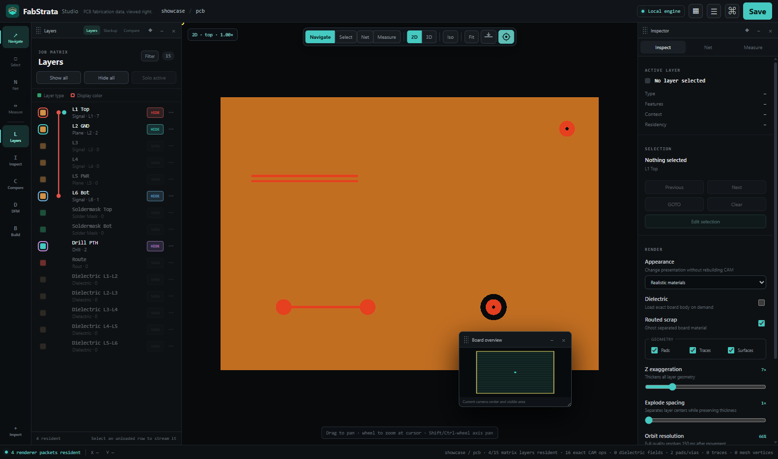
Show exact 2D artwork together with the real layer matrix and visibility controls.
Exact 2D artwork with the live layer matrix, per-row visibility, and the board overview.
Exact 2D artwork
Pan, zoom to cursor, fit, coordinate readout, and a top/bottom flip that uses the correct physical paint order for the side you are viewing.
Physical-stackup 3D
Copper at physical Z, dielectric and soldermask, plating, realistic holes, routed scrap, and cross-sections — built from the same geometry as the 2D view.
Real hole and route geometry
Drill and route features cut visible openings; a plated slot is a walled channel through the board rather than a flat marker.
Presentation controls
Dielectric visibility, feature-class filters, layer colour, opacity, polarity, conformal drape, Z exaggeration, and exploded-stack spacing that preserves authored thickness.
Correctness before cosmetics
Level of detail, culling, tiling, and caching may change cost — never board meaning, connectivity, or picking accuracy.
Cross-section tool

Place a cut line and inspect the board through its depth.

Choose Section from the main toolbar and pick two points on the 2D board. FabStrata calculates the copper, dielectric, plating, holes, and routed geometry along that cut.

Place the cutPick two endpoints directly on the 2D board.
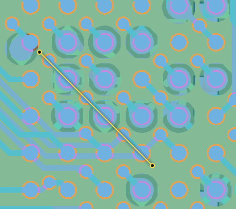
Show the real 2D board viewport while an operator places the two endpoints of a board cross-section.
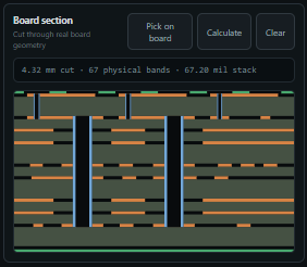
Inspect the stackRead the physical bands, holes, and measured stack.
Show the calculated FabStrata board-section panel produced from the selected cut line.
03

Stackup and layer matrix

The physical build is an editable, inspectable object, not a static list of files.

Named layer matrix
Rows carry the source filename by default, a material swatch, a display colour, visibility, and per-row colour, opacity, polarity, and context controls.
Editable physical stack
Reorder layers, change type and material, set thickness, place dielectrics at their real positions, and review the calculated cross-section.
Interactive board section
Open Build → Physical → Board section, place two points on the 2D board, and inspect the copper, dielectric, plating, holes, and routed geometry along that cut.
Drill and route spans
A compact span rail on every drill and route row: drag the endpoints to set the first and last conductor reached, with exact values and the method behind them in the detail popover.
Steps, nesting, and regions
One job-global stack across many steps, with step-and-repeat panelisation, nesting, regions, and profiles.
04

Connectivity and netlist

Nets that follow the copper, so the board tells you what it is actually connected to.

Net isolation

From the whole board to one connected path.

Highlight a net in context, then isolate it across every copper layer and plated span it touches.
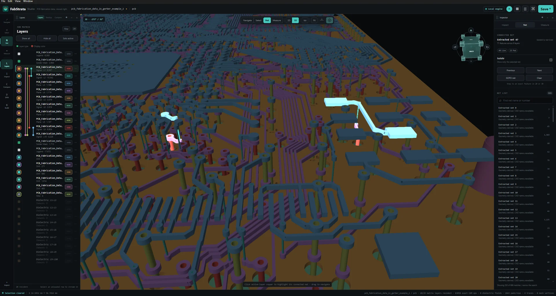
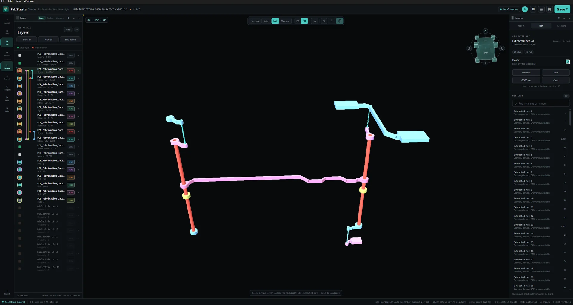
Show a selected physical net highlighted in context across the visible board stack before isolation is enabled.Show the same physical net isolated across the relevant stack layers after isolation is enabled.
The selected net stays bright while the surrounding board remains visible.
Physical net extraction
Connectivity is derived from resolved copper and plating. A plated slot unites the layers it touches; routed scrap falls out of the net because it falls out of the board.
Highlight and isolation
Search, highlight, isolate, GOTO, and deterministic previous/next traversal across every layer involved. Large planes participate as full copper regions.
IPC-D-356 comparison
Import a reference netlist and compare it against the extracted physical connectivity.
Honest staleness
A span, plating, or geometry edit marks connectivity stale; the rebuild is deferred until a connectivity-dependent action asks for it, then the derived netlist refreshes once.
05

Revision and layer comparison

Show exactly what moved between two releases of the same board.

Canonical layer pairing
Choose or import a revision step and pair the two canonical layer matrices before the comparison runs.
Geometry difference
Added, removed, moved, and resized geometry in distinct A and B colours, with both involved layers visible when you navigate to a difference.
Navigable findings
Step through differences region by region without losing the tool or workspace you started from.
06

Measurement, analysis, and review workspaces

The checks a front-end engineer runs on incoming data, in the same session as the artwork.

Measurement
Aligned, horizontal, vertical, baseline, chain, ordinate, leader, angle, radius, and diameter dimensions with snapping, tolerances, notes, and supported one-way driving constraints. The constraint solver is sequential and one-way.
Drills and tools
Tool rows reconciled to exact visible hits, including route and slot operations, plating, span, count, and warnings, with select and GOTO from any row.
Apertures
D-code and symbol usage for the active layer.
Impedance
Selected-trace analysis with a stack-aware calculator, target values, and an audit of what the result was derived from.
DFM
Author supported rules, run checks, filter findings, navigate and select the implicated geometry, and persist waivers.
Quote and fab notes
Extracted declarations with their method, confidence, and reconciliation, and a GOTO back to the source. Measured, structured, declared, reconciled, and experimental data stay visually distinct.
07

Projects, reports, and exports

Review work that survives the session and travels to people without FabStrata.

Project persistence
Source names, roles, contexts, polarity, units and coordinates, spans, physical order, and every operator decision survive save and reopen in a .fabio project.
Undo, redo, and history
Every document mutation is a journaled command with an explicit history class, plus an action history you can read.
Review exports
A self-contained HTML report, a composite PNG, per-layer check films, and a GLB of the physical stack.
Bounded recovery
Renderer or device loss, stale derived data, partial imports, and unsupported project versions produce a bounded recovery path and an actionable error rather than undefined state.

Review exports

  • HTML reportSelf-contained review report that opens without FabStrata installed.
  • Composite PNGThe 2D composite as currently presented.
  • Check filmsPer-layer check film images.
  • GLBThe physical stack as 3D geometry. It approximates some macro pads and omits semantic text geometry.

These are review outputs. FabStrata does not write fabrication Gerber, NC, ODB++, or IPC-2581 data.

Why FabStrata

Built so the answer is checkable.

Evidence, not guesswork

Names, extensions, and headers are evidence. Content and geometry confirm or contradict them, and the confidence, method, and original observation stay attached to every interpretation.

One kernel below the interface

Exact geometry and manufacturing state live in a headless kernel, so the 2D view, the 3D view, and a connectivity query cannot disagree about the board.

Board work stays on your machine

Import, geometry, connectivity, rendering, projects, and review exports are computed on the operator’s computer. Customer fabrication data is not uploaded to FabStrata.

Who it is for

People who are accountable for the data.

CAM and front-end engineers

Interrogate an incoming package, reconcile drill tools to real hits, and resolve contradictory declarations with the evidence in front of you.

PCB designers

Confirm the deliverable you are about to release says what you think it says — stackup, spans, polarity, nets, and fab notes included.

Contract manufacturers and board houses

Run the same incoming-data and revision review on every job, and hand back a report that shows what you found.

Engineering and quality teams

Verify connectivity against an IPC-D-356 reference and keep a durable, exportable record of the review.

Product focus

Built for fabrication review.

FabStrata stays focused on understanding and reviewing manufacturing data. These adjacent workflows are intentionally outside that focus.

PCB design and schematic capture
FabStrata reviews the fabrication deliverable. It is not a design tool.
Broad CAM authoring and fabrication output
FabStrata reads manufacturing data; it does not export fabrication Gerber, NC, ODB++, or IPC-2581 output.
Components, BOM, and assembly
Component placement, bills of material, and assembly workflows are outside its focus.
IPC-2581 and STEP input
Neither format is currently imported.
Path-traced production rendering
The 3D view is an inspection view. Offline photorealistic rendering is reserved for a later renderer.
Silent resolution of contradictions
FabStrata will not quietly pick a winner when manufacturing declarations disagree. It shows you the conflict.